Home » AC Servo Motor » What is Position Control by AC Servo?
What is Position Control by AC Servo?
The methods for stopping a moving object with prescribed accuracy at a fixed position consist of a mechanical method and an electrical method. Mechanical methods generally include putting a stopper (inverter stopping control and AC servo motor torque limiting are up to contact with the stopper) and forcible positioning methods of inserting an object into the cylinder, but there are restrictions on the stopping position. On the other hand, with an electrical method, positioning at many optional positions is easy by employing position sensors. Electrical positioning also has various met hods depending on the position detection method and the control method, and these are broadly classified into the speed control methods and position control methods mentioned below.
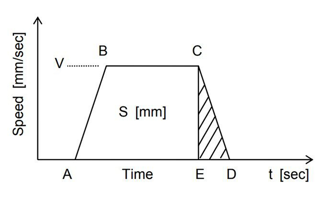
When a mobile object operated by the motor stops automatically, the position is normally detected by the limit switch and the motor is stopped by that signal (often resulting in simultaneous braking). Figure 1 shows the relation of speed against time of a mobile object. If the horizontal axis is time (sec) and the vertical axis is speed (mm/sec), the area enclosed by the speed pattern constitutes the travel distance (mm).

After operation of the limit switch, the coasting distance is equivalent to the area CDE, and the stopping precision becomes the variations in this area CDE. The factors (causes of variations in area CDE) affecting stopping precision are, stop time (ED) changes (load torque fluctuations or brake torque fluctuations), as shown in Figure 2, speed fluctuations of moving objects at point C, and variations in the sensor operating position at point C as well as variations in delay time until the start of actual motor deceleration due to sensor operation.

These variations in characteristics certainly need to be reduced, but the most effective method would be to reduce the V speed. Thus, when the stopping precision is not satisfactory during stopping from normal speed, a general method is to set a limit switch for low speed switching and to stop once the speed is lowered. This method is simple and widely used to increase the precision. However, a drawback is that if the specified time (called creep speed) at low speeds is inadequate, the speed while passing the stop limit switch will be unstable due to load fluctuations, and it will take time for positioning. Also, if the stop positions are increased, a larger number of sensors will be required.
2. Pulse count method
There is a pulse count method in which the limit switch method is improved. With this method, time can be minimized for short distance movements to obtain deceleration points at several stages by selecting any stop position. The stopping precision itself does not change as with the limit switch method, but the current position of a moving object is always detected. Thus, when the stop position is exceeded, compensation is easily possible.
However, the factors that influence stopping precision have similar problems as with the limit switch method. Therefore, a significant improvement to the stopping precision itself cannot be expected.
3. Pulse command method
In the positioning method used by the servo, the above mentioned drawbacks are removed (improved), and the position of a moving object is always detected similar to in the pulse count method. In this method, setting a low speed creep speed during a stop is not required, the speed is continuously controlled from high speeds to a direct stop target position, and stopping is done with the required precision. This method is called the position control method with respect to the speed control method.
- Speed control method. There is no signal output device required for positioning in the motor, and a device such as a limit SW exists for backing up on the machine side.
- Positioning control method. There is no device for position detection on the machine side, and highly accurate position control is carried out by the encoder on the servo motor side.
When a mobile object operated by the motor stops automatically, the position is normally detected by the limit switch and the motor is stopped by that signal (often resulting in simultaneous braking). Figure 1 shows the relation of speed against time of a mobile object. If the horizontal axis is time (sec) and the vertical axis is speed (mm/sec), the area enclosed by the speed pattern constitutes the travel distance (mm).

Figure 1
After operation of the limit switch, the coasting distance is equivalent to the area CDE, and the stopping precision becomes the variations in this area CDE. The factors (causes of variations in area CDE) affecting stopping precision are, stop time (ED) changes (load torque fluctuations or brake torque fluctuations), as shown in Figure 2, speed fluctuations of moving objects at point C, and variations in the sensor operating position at point C as well as variations in delay time until the start of actual motor deceleration due to sensor operation.

Figure 2
These variations in characteristics certainly need to be reduced, but the most effective method would be to reduce the V speed. Thus, when the stopping precision is not satisfactory during stopping from normal speed, a general method is to set a limit switch for low speed switching and to stop once the speed is lowered. This method is simple and widely used to increase the precision. However, a drawback is that if the specified time (called creep speed) at low speeds is inadequate, the speed while passing the stop limit switch will be unstable due to load fluctuations, and it will take time for positioning. Also, if the stop positions are increased, a larger number of sensors will be required.
2. Pulse count method
There is a pulse count method in which the limit switch method is improved. With this method, time can be minimized for short distance movements to obtain deceleration points at several stages by selecting any stop position. The stopping precision itself does not change as with the limit switch method, but the current position of a moving object is always detected. Thus, when the stop position is exceeded, compensation is easily possible.
However, the factors that influence stopping precision have similar problems as with the limit switch method. Therefore, a significant improvement to the stopping precision itself cannot be expected.
3. Pulse command method
In the positioning method used by the servo, the above mentioned drawbacks are removed (improved), and the position of a moving object is always detected similar to in the pulse count method. In this method, setting a low speed creep speed during a stop is not required, the speed is continuously controlled from high speeds to a direct stop target position, and stopping is done with the required precision. This method is called the position control method with respect to the speed control method.
Post a Comment:
You may also like:

Category
Featured Articles
What is Operation Principle of AC ...
 The output torque of the servo motor is proportional to the current that flows in the motor. Because the servo amplifier normally ...
 The output torque of the servo motor is proportional to the current that flows in the motor. Because the servo amplifier normally ...
AC Servo Motor: Structure, Working and ...
 AC servo motor is a type of motor widely used in various industrial and commercial fields. It features high precision,fast ...
 AC servo motor is a type of motor widely used in various industrial and commercial fields. It features high precision,fast ...
How to Wire an AC Servo Motor?
 A servo motor is a type of motor that allows precise control of position, speed, and acceleration through a controller. The ...
 A servo motor is a type of motor that allows precise control of position, speed, and acceleration through a controller. The ...
What is Position Control by AC Servo?
 The methods for stopping a moving object with prescribed accuracy at a fixed position consist of a mechanical method and an ...
 The methods for stopping a moving object with prescribed accuracy at a fixed position consist of a mechanical method and an ...