Home » DC Servo Motor
Brushless DC servo motor with 100W, 3000 rpm rated speed, no-load speed up to 3300 rpm, 5.4A at 24V DC voltage, rated torque of 0.31 Nm and peak torque of 0.95 Nm, 2500PPR incremental encoder attached.


A 200W 24V DC servo motor is specifically crafted for servo applications, featuring a power rating of 200 watts and an operational voltage of 24 volts. This high-precision motor is available for purchase and comes with detailed specifications, including a rated torque of 1.27 Nm, a rated speed of 1500 rpm, an 80mm flange size, and is equipped with a 2500 PPR incremental encoder. This brushless DC servo motor is well-suited for industrial CNC machines, where precision and reliable performance are paramount. The combination of its power capacity, voltage compatibility, and advanced features make it an optimal choice for applications requiring accurate control and responsiveness in industrial settings.


ATO provides 400W DC servo motors with IP55 protection and class F insulation in a ruggedized enclosure. DC servo motors are special motors made of NdFe35 permanent magnet material, which has strong demagnetization resistance and stable motor performance. 24V DC servo motors have the superior performance of low vibration, low noise and low inertia, so they are commonly used in numerical control machine tools, automated production lines, and medical equipment.
ATO, as a professional manufacturer of servo motors, provides the right servo motor selection knowledge for customers in need. According to the actual needs to choose the right type of motor and specifications, such as motor size, output power, voltage, current and so on. Next ATO introduces a high performance 500W DC servo motor.
ATO suppliers now sell 1000W DC servo motors. The DC servo motor is a motor with high control accuracy and fast response speed. It can maintain torque at a height of 6.3 Nm, has a rated speed of 1500 rpm, and has a high no-load speed. DC servo motors equipped with 2500 PPR incremental encoders are low cost, easy to use and portable. Heavy-duty DC servo motors are of excellent quality and have the advantages of high peak torque, low noise, low temperature rise, and low current consumption. Brushless DC motors are widely used in mechanical processing, automation control and other fields.
ATO supplier provides 1500W DC servo motor. When selecting a DC servo motor, you need to select appropriate performance parameters based on actual needs. The DC servo motor with a rated speed of 1500 rpm and a no-load speed of up to 1700 rpm is a motor that generates torque based on DC power. It has the advantages of fast response, high-precision control, reliability, etc., so it has been widely used in many fields. The 1500W brushless DC servo motor has a 110mm square flange and is equipped with a 2500 PPR incremental encoder. Sturdy structure, light weight, easy to carry and use, can achieve low rotation speed and high torque.
In this article, the primary learning objectives are outlined, with a focus on understanding and applying key concepts related to DC servomotors. First and foremost, the reader is expected to be able to draw the equivalent DC servomotor circuit theory model. Subsequently, the article aims to facilitate the comprehension of the equations of motion utilized for deriving the electromechanical transfer function in both the time domain and the s-domain. Additionally, readers are encouraged to master the skill of drawing the DC servomotor signal block diagram. Lastly, the article guides individuals through the process of deriving the DC servomotor electromechanical transfer function, ensuring a comprehensive understanding of this critical aspect of control systems.
Parameters vary with time due to the depreciation and aging effect which reduces performance, therefore, to overcome this problem, motor parameters should be updated and different techniques should be used for this purpose. All the previously developed methods are built upon parameter knowledge of the accurate model.
The techniques presented in the literature are much complex and require huge computational costs making these unattractive for common DC servo motor parameter estimation purposes. The contributions of the article are summarized as:
(1) The first-principle model of the DC servo motor is developed and comparing coefficients method has been used to determine the system parameters.
(2) The parameter estimation toolbox has been used to estimate the parameters and validate the response of the system.
(3) A system identification toolbox has been used to estimate parameters.
(4) Comparison of the three methods has been carried out to select the best option for such applications.
Experimental data has been used for the comparison of the estimated response from the techniques. The results show that the parameters obtained from the parameter estimation method give the most accurate simulation results with the least error against the experimental results.

A plot of T/TM versus ω/ωM characteristics with VT/VTm as a parameter is shown in the following picture. The curves are non-dimensionalized and based on Eq. (11).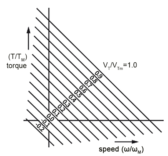
The curves can be dimensionalized if the manufacturer's data for a particular motor are known. For example, a DC servo motor has an armature resistance of 5 ohms and a no-load speed of 3000 rpm at a maximum armature terminal voltage of 90 volts.
To dimensionalize a plot of T/TM versus ω/ωM characteristics, find the value of no-load speed
ωM in radians/sec and the value of stall torque TM.
From Eq. (1), ω is defined as 2ω X rpm/60. At no-load speed, ω= ωM which is:
ωM= 2π X 3000/60
= 314 radians/sec
When choosing a servo motor, it is important to have a good understanding of the system to be controlled. In DC servo motor operation, the control algorithm is paramount to the improvement of transient response times reduction of steady-state errors, and sensitivity to load parameters.
Servo control can generally be broken down into two classes of problems: Command tracking and disturbance rejection. The first pertains to how well the actual motion follows the position, velocity, acceleration, and torque commands. The second can include anything from torque disturbance on the motor shaft to supply voltage variations.
PID (Proportional Integral and Derivative) and PIV (Proportional Integral and Velocity) loops are the most common controller strategies employed. Unlike Feed-Forward control, which can anticipate the internal commands for zero error following, disturbance rejection reacts to unknown disturbances and modeling errors. To improve the overall performance, both of these control types can be combined.

The servo control technique is one of the key technologies in the field of control like robots. In order to meet the demands of servo control for robots, a DSP-based DC servo motor control system was developed. Firstly, this paper promoted the design of the controller an danalyzed the overall structure and function of the system. Then the hardware of the system was introduced and the key components were chosen and demonstrated; the classical PID algorithm was selected as the core algorithm of servo control and the design of the system program was elaborated. Finally, an experiment was conducted on the hardware platform with software systems.


A DC servo motor along with servomechanism acts as a servo motor which is basically used as a mechanical transducer in the automation industry. Based on its accurate closed-loop control, it has versatile applications used in many industries. The DC servo motor definition is, a motor that is used in servo systems is known as a servo motor. A servo system is a closed-loop system where the feedback signal (position, velocity, acceleration, etc.) drives the motor. This signal acts as an error and based on controller, accurate position or velocity is achieved. The motors are coupled to an output shaft through a gear train for power matching.
Category
Featured Articles
What is a Servo Motor?
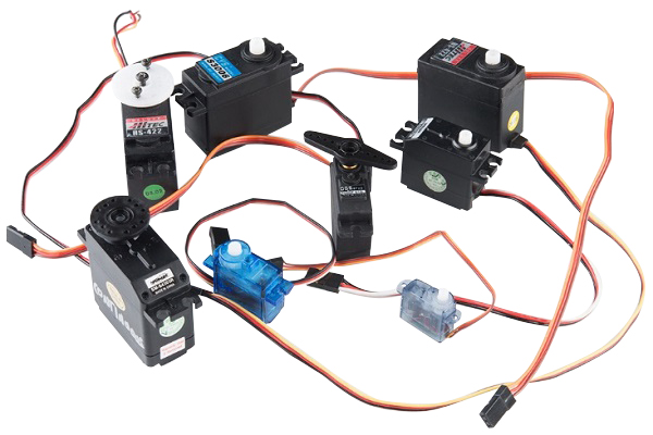 There are some special types of application of electrical motor where rotation of the motor is required for just a certain angle ...
 There are some special types of application of electrical motor where rotation of the motor is required for just a certain angle ...
What are the Basics of Servo Drive?
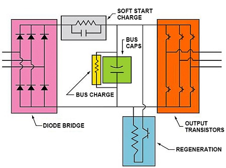 Servo motors come in so many types and flavors that it is difficult to define them in a way that is accurate and universally ...
 Servo motors come in so many types and flavors that it is difficult to define them in a way that is accurate and universally ...
Why Use Servo Motor as Test Load?
 Dynamometer is mainly divided into two parts: cabinet and frame, while the frame mainly has the motor under test, torque speed ...
 Dynamometer is mainly divided into two parts: cabinet and frame, while the frame mainly has the motor under test, torque speed ...
What Should Consider Before Using ...
 Servo system is a commonly used control system, widely used in industrial automation. It compares the output signal with the ...
 Servo system is a commonly used control system, widely used in industrial automation. It compares the output signal with the ...
Servo Motor in Food Industry
 In the ever-evolving landscape of the food industry, technological advancements play a pivotal role in enhancing efficiency, ...
 In the ever-evolving landscape of the food industry, technological advancements play a pivotal role in enhancing efficiency, ...