Home » Servo Drive » What are the Soft Start Techniques for Driving Servos?
What are the Soft Start Techniques for Driving Servos?
Servos (as commonly used in radio-controlled vehicles and small-scale robotics)are DC actuators that use a potentiometer to provide built in feedback to localize an actuator arm. To minimize jerky control movements, many servo controllers include velocity and acceleration control which operate using a defined velocity profile resulting in the Pulse Width Modulation (PWM) control value being changed over time. On power-up, the initial position of the servoarm is unknown to the external controller-resulting in the arm moving to the starting value at maximum speed (which may be mechanically hazardous). In this paper, two different techniques for performing a soft-start for servos are described and evaluated, namely: voltage profiling and intermittent drive.
Introduction
Remote Control (RC) servo motors are small feedback actuators consisting of a driver, motor, and a feedback potentiometer which is used to precisely control the position of an armature connected to the motor via a series of gear. For the purpose of clarity, these internal feedback servo motors will be referred to as servos throughout this paper as distinct from traditional servomotors which tend to use an encoder to provide feedback of velocity and armature position rather than simply position. Servos offer a high torque revolute control system in an inexpensive, small package allowing simple control using a Pulse Width Modulated (PWM) signal.
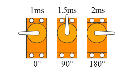
These servos have many applications including manipulating control surfaces for Unmanned Vehicles, haptic feedback, panning sensors in robotics and general robotic motion control for locomotion and manipulation. The internal servo driver uses an H-Bridge to provide bi-directional motor control. The current position of the motor is provided to the internal driver by way of a potentiometer which is connected to the servo gearing system. A PWM signal is used to drive the servo, typically with a period of 20ms and a pulse width varying from 1ms to 2ms corresponding to the desired servo armature position.

More recently, digital servos have been developed which use a micro controller to interpolate control signals to drive the DC motor at a frequency of 300Hz (as opposed to 50Hz for analog servos). This increased frequency reduces the servo dead band and provides faster response, constant torque, and more holding power when stationary. Additionally, some digital servos are programmable-allowing factors such as acceleration, end-point, center-point, and velocity to be controlled. This programming can significantly affect the functionality required from the servo controller (as the micro controller in the servo driver regulates these parameters).
 Servos tend to have a reasonably high rotational velocity (in the order of 350°/s). Although this relatively fast rotational speed is useful in some applications (e.g. UAV control surfaces), some applications including precisely panning robotic sensors or controlling a robotic manipulator may require a slower velocity and/or acceleration. Many dedicated servo controllers pro-vide programmable functionality for both velocity profiling and acceleration profiling. Velocity profiling can be of particular use when the servo is driving a relatively heavy load by allowing a slower velocity to minimise potential mechanical wear and reduce large current in-rush through the system.
Commercial servo controllers perform profiling by periodically changing the PWM position between the previous desired position and the next desired position. Using this method ensures that the servo doesn’t attempt to move instantaneously to the end position but rather moves through a series of programmed intermediate steps before settling at the final desired position.
One problem faced by servo controllers is that the initial position of the servo (although known internally to the servo) is not known by the system driving the servo. Hence, a servo controller may have acceleration and velocity profiling configured, but as the starting position is unknown it can’t slowly step the servo to the new desired position—resulting in the servo snap-ping to the position at full velocity. For some applications this may resulting additional wear on components, but for some applications (like hexapod walking robots) the start-up routine may cause some legs to damage other legs if various legs or joints collide on high speed at start-up.
 Voltage Profiling
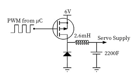
The proposed voltage profiling technique seeks to limit the supply voltage provided to the servo for a short period of time as the servo turns on. This is similar to traditional digital motor control techniques where some form of modulation allows proportional control over the motor. The implementation of the voltage profiling uses a P-Channel Metal-Oxide-Semiconductor Field-Effect Transistor (MOSFET) which is driven by a PWM output on the micro controller with a frequency of 200kHz. A LC (Inductor-Capacitor) first order Low Pass Filter (LPF) with a cut-off frequency of 66Hz is attached to the output of the MOSFET to filter the switching noise in order to provide the servo with a sufficiently stable DC voltage. As the voltage is controlled by the micro controller using PWM (a common technique for Digital to Analog Conversion), a wide variety of voltages can be produced to supply power to the servo.
Intermittent Drive
The proposed intermittent drive soft-start servo technique seeks to implement a soft-start without using any additional circuitry (unlike the volt-age profiling technique). The servo motors essentially internally use a bidirectional form of bang-bang control as is common for some motor control operations. The intermittent drive technique essentially inserts a fixed length delay between the on-periods of the controller to reduce the servo angular velocity. This was achieved by maintaining a constant full scale supply voltage (of 6V) whilst intermittently sending the control signal to the servo. Rather than sending the PWM signal to the servo with a 20ms period as specified in the servo data sheet, this method allows multiple control pulses to be skipped.
 Rather than slowing down the actual speed of the motor as is done for voltage profiling, the intermittent drive technique seeks to pulse the motor so that the motor will run at full speed, but only for a short time. This results a decreased mean velocity as the servo moves to the desired position in a series of short jumps.
This paper has demonstrated and evaluated two different techniques in order to provide soft-start functionality to servos. Firstly, voltage profiling requires additional hardware to control the supply voltage used to power the servo. The segmented ramping approach seemed to be the most effective profile, providing a good balance between keeping acceleration to a maximum and maintaining a moderate overall velocity. The second technique, intermittent drive, requires no additional hardware but only works for analog servos and results in significant current spikes being induced into the system. Using either of these soft-start techniques, servo motors should no longer need to move at full speed to their starting position on power up potentially damaging what they are connected to. Just as many commercial servo controllers have programmable velocity and acceleration control, the techniques in this paper enable soft-start for servos, an advance which gives significantly enhanced operational control.
Introduction
Remote Control (RC) servo motors are small feedback actuators consisting of a driver, motor, and a feedback potentiometer which is used to precisely control the position of an armature connected to the motor via a series of gear. For the purpose of clarity, these internal feedback servo motors will be referred to as servos throughout this paper as distinct from traditional servomotors which tend to use an encoder to provide feedback of velocity and armature position rather than simply position. Servos offer a high torque revolute control system in an inexpensive, small package allowing simple control using a Pulse Width Modulated (PWM) signal.
These servos have many applications including manipulating control surfaces for Unmanned Vehicles, haptic feedback, panning sensors in robotics and general robotic motion control for locomotion and manipulation. The internal servo driver uses an H-Bridge to provide bi-directional motor control. The current position of the motor is provided to the internal driver by way of a potentiometer which is connected to the servo gearing system. A PWM signal is used to drive the servo, typically with a period of 20ms and a pulse width varying from 1ms to 2ms corresponding to the desired servo armature position.


Commercial servo controllers perform profiling by periodically changing the PWM position between the previous desired position and the next desired position. Using this method ensures that the servo doesn’t attempt to move instantaneously to the end position but rather moves through a series of programmed intermediate steps before settling at the final desired position.
One problem faced by servo controllers is that the initial position of the servo (although known internally to the servo) is not known by the system driving the servo. Hence, a servo controller may have acceleration and velocity profiling configured, but as the starting position is unknown it can’t slowly step the servo to the new desired position—resulting in the servo snap-ping to the position at full velocity. For some applications this may resulting additional wear on components, but for some applications (like hexapod walking robots) the start-up routine may cause some legs to damage other legs if various legs or joints collide on high speed at start-up.

The proposed voltage profiling technique seeks to limit the supply voltage provided to the servo for a short period of time as the servo turns on. This is similar to traditional digital motor control techniques where some form of modulation allows proportional control over the motor. The implementation of the voltage profiling uses a P-Channel Metal-Oxide-Semiconductor Field-Effect Transistor (MOSFET) which is driven by a PWM output on the micro controller with a frequency of 200kHz. A LC (Inductor-Capacitor) first order Low Pass Filter (LPF) with a cut-off frequency of 66Hz is attached to the output of the MOSFET to filter the switching noise in order to provide the servo with a sufficiently stable DC voltage. As the voltage is controlled by the micro controller using PWM (a common technique for Digital to Analog Conversion), a wide variety of voltages can be produced to supply power to the servo.
Intermittent Drive
The proposed intermittent drive soft-start servo technique seeks to implement a soft-start without using any additional circuitry (unlike the volt-age profiling technique). The servo motors essentially internally use a bidirectional form of bang-bang control as is common for some motor control operations. The intermittent drive technique essentially inserts a fixed length delay between the on-periods of the controller to reduce the servo angular velocity. This was achieved by maintaining a constant full scale supply voltage (of 6V) whilst intermittently sending the control signal to the servo. Rather than sending the PWM signal to the servo with a 20ms period as specified in the servo data sheet, this method allows multiple control pulses to be skipped.

This paper has demonstrated and evaluated two different techniques in order to provide soft-start functionality to servos. Firstly, voltage profiling requires additional hardware to control the supply voltage used to power the servo. The segmented ramping approach seemed to be the most effective profile, providing a good balance between keeping acceleration to a maximum and maintaining a moderate overall velocity. The second technique, intermittent drive, requires no additional hardware but only works for analog servos and results in significant current spikes being induced into the system. Using either of these soft-start techniques, servo motors should no longer need to move at full speed to their starting position on power up potentially damaging what they are connected to. Just as many commercial servo controllers have programmable velocity and acceleration control, the techniques in this paper enable soft-start for servos, an advance which gives significantly enhanced operational control.
Post a Comment:
You may also like:

Category
Featured Articles
What are the Basics of Servo Drive?
 Servo motors come in so many types and flavors that it is difficult to define them in a way that is accurate and universally ...
 Servo motors come in so many types and flavors that it is difficult to define them in a way that is accurate and universally ...
How to Install a Servo Drive?
 Installing a servo drive involves several steps, and the specific process may vary depending on the manufacturer and model of the ...
 Installing a servo drive involves several steps, and the specific process may vary depending on the manufacturer and model of the ...
Servo Drive System vs. Variable ...
 A servo drive system, as opposed to a variable frequency drive (VFD) or AC motor drive , has the ability to position with ...
 A servo drive system, as opposed to a variable frequency drive (VFD) or AC motor drive , has the ability to position with ...
What are the Soft Start Techniques for ...
 Servos (as commonly used in radio-controlled vehicles and small-scale robotics)are DC actuators that use a potentiometer to ...
 Servos (as commonly used in radio-controlled vehicles and small-scale robotics)are DC actuators that use a potentiometer to ...