Home » Servo Drive » What are the Basics of Servo Drive?
What are the Basics of Servo Drive?
Servo motors come in so many types and flavors that it is difficult to define them in a way that is accurate and universally acceptable. It is possible, though, to describe some of the things commonly found in servo drives, as well as typical configurations. Servo drives are designed to convert electrical power into precision controlled motion, controlled torque (torque servo), controlled speed (velocity servo) or controlled position (positioning servo). This typically requires at least three elements: the motor, feedback of some sort, and an amplifier.
DC brush motors
DC motors can be either rotary or linear. Rotary DC motors typically are long and thin, which allows for quick acceleration due to the lower inertia, as well higher speed due to the lower centrifugal forces of a smaller diameter armature. The armature is skewed to help reduce low-speed "velocity ripple." Linear DC motors have the commutator and windings along the path of travel, and power may be supplied to the brushes by a bus bar or an umbilical cord. The "moving short" with the brushes has a permanent magnet, which is attracted to the energized stationary coil. A linear bearing is used to create an air gap and low friction.
 AC induction servo motors
AC induction servo motors can be linear or rotary. The rotary design typically is long and thin, making it suitable for higher speeds and quicker acceleration and deceleration profiles due to the lower inertia. A separate constant-velocity blower motor is often attached to the back of the servo motor for cooling during low-speed operation. The stator has a standard, low-inductance, three-phase AC motor winding, which sometimes has special volts/hertz ratings and/or wye-delta switching.
Linear induction servo motors operate from the same principle as rotary induction motors. They have a three phase coil (typically on the moving short) powered by an umbilical cord or bus bar and ride on two linear bearings above an aluminum "reaction plate" that is mounted on steel. The advantage of linear induction servo motors over brushless servo motors is their maximum speed. Since they do not have to fight the back EMF (electromotive force) of the motor through the magnets, they can reach velocities of more than 2000 in/sec (5080 cm/sec) or 110 miles/hour (177 km/hr) with enough travel.
 Feedback
Servo systems receive feedback from the motor and sometimes from the product and/or process. The focus of this article is servo drives, so elements of process feedback are not included. Brush-style rotary DC servo motors may use tachometer feedback (typically 7 volts/1000 rpm), encoder feedback, and/or resolver feedback. Brush-style linear DC servo motors use encoder or laser feedback. Brushless rotary DC servo motors may use hall feedback and/or encoder feedback, or resolver feedback. Brushless linear DC motors may use linear encoder feedback with halls or sinusoidal commutated linear encoder feedback. Induction rotary motors use a rotary encoder, whereas induction linear motors use a linear encoder. Brief descriptions of the various feedback devices can be helpful in understanding how they work.
The Amplifier
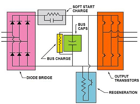
The amplifier converts the output power from the distribution panel to controlled output that will cause the motor to move at the correct velocity. Most servo amplifiers are PWM (pulse width modulated) style. The converter section of a single-axis amplifier uses a diode bridge to change AC input power to DC power, which is then "smoothed out" by the addition of a capacitor. This DC section is called the bus. The output is then "chopped up" by transistors (typically FETs or IGBTs). These devices rapidly turn the DC power to the motor on and off. If the transistor is closed for long periods (motor receiving power) with short open periods (motor not receiving power), the average terminal voltage goes up. If the transistor is open for long periods (motor not receiving power) and closed for shorter periods (motor receiving power), the average voltage goes down. The amplifier can close an "upper transistor" in one phase and a "lower transistor" in another phase, creating a path through the winding. If the motor is AC, the polarities can be reversed by switching from an upper to a lower transistor and back on each of the phases.
 Conclusions
There are many parts to a servo system that are individually critical yet interrelated. The motor is the prime mover; it converts electrical energy into either rotational or linear movement. The speed feedback monitors the velocity of the motor. The current feedback closes the torque loop. The position feedback tracks the location of the load. The amplifier converts the line power to a different voltage and/ or frequency to control the current and velocity of the motor and load. The controller is the brain of the operation, calculating the trajectory, comparing with the feedback and correcting for error. Successful installation and operation of servo systems/requires people with good mechanical, electrical, electronic, application and programming experience and capabilities. It also is important to allow time for tuning the system, and to expect programming bugs.
DC brush motors
DC motors can be either rotary or linear. Rotary DC motors typically are long and thin, which allows for quick acceleration due to the lower inertia, as well higher speed due to the lower centrifugal forces of a smaller diameter armature. The armature is skewed to help reduce low-speed "velocity ripple." Linear DC motors have the commutator and windings along the path of travel, and power may be supplied to the brushes by a bus bar or an umbilical cord. The "moving short" with the brushes has a permanent magnet, which is attracted to the energized stationary coil. A linear bearing is used to create an air gap and low friction.

AC induction servo motors can be linear or rotary. The rotary design typically is long and thin, making it suitable for higher speeds and quicker acceleration and deceleration profiles due to the lower inertia. A separate constant-velocity blower motor is often attached to the back of the servo motor for cooling during low-speed operation. The stator has a standard, low-inductance, three-phase AC motor winding, which sometimes has special volts/hertz ratings and/or wye-delta switching.
Linear induction servo motors operate from the same principle as rotary induction motors. They have a three phase coil (typically on the moving short) powered by an umbilical cord or bus bar and ride on two linear bearings above an aluminum "reaction plate" that is mounted on steel. The advantage of linear induction servo motors over brushless servo motors is their maximum speed. Since they do not have to fight the back EMF (electromotive force) of the motor through the magnets, they can reach velocities of more than 2000 in/sec (5080 cm/sec) or 110 miles/hour (177 km/hr) with enough travel.

Servo systems receive feedback from the motor and sometimes from the product and/or process. The focus of this article is servo drives, so elements of process feedback are not included. Brush-style rotary DC servo motors may use tachometer feedback (typically 7 volts/1000 rpm), encoder feedback, and/or resolver feedback. Brush-style linear DC servo motors use encoder or laser feedback. Brushless rotary DC servo motors may use hall feedback and/or encoder feedback, or resolver feedback. Brushless linear DC motors may use linear encoder feedback with halls or sinusoidal commutated linear encoder feedback. Induction rotary motors use a rotary encoder, whereas induction linear motors use a linear encoder. Brief descriptions of the various feedback devices can be helpful in understanding how they work.
The Amplifier
The amplifier converts the output power from the distribution panel to controlled output that will cause the motor to move at the correct velocity. Most servo amplifiers are PWM (pulse width modulated) style. The converter section of a single-axis amplifier uses a diode bridge to change AC input power to DC power, which is then "smoothed out" by the addition of a capacitor. This DC section is called the bus. The output is then "chopped up" by transistors (typically FETs or IGBTs). These devices rapidly turn the DC power to the motor on and off. If the transistor is closed for long periods (motor receiving power) with short open periods (motor not receiving power), the average terminal voltage goes up. If the transistor is open for long periods (motor not receiving power) and closed for shorter periods (motor receiving power), the average voltage goes down. The amplifier can close an "upper transistor" in one phase and a "lower transistor" in another phase, creating a path through the winding. If the motor is AC, the polarities can be reversed by switching from an upper to a lower transistor and back on each of the phases.

There are many parts to a servo system that are individually critical yet interrelated. The motor is the prime mover; it converts electrical energy into either rotational or linear movement. The speed feedback monitors the velocity of the motor. The current feedback closes the torque loop. The position feedback tracks the location of the load. The amplifier converts the line power to a different voltage and/ or frequency to control the current and velocity of the motor and load. The controller is the brain of the operation, calculating the trajectory, comparing with the feedback and correcting for error. Successful installation and operation of servo systems/requires people with good mechanical, electrical, electronic, application and programming experience and capabilities. It also is important to allow time for tuning the system, and to expect programming bugs.
Post a Comment:
You may also like:

Category
Featured Articles
What are the Soft Start Techniques for ...
 Servos (as commonly used in radio-controlled vehicles and small-scale robotics)are DC actuators that use a potentiometer to ...
 Servos (as commonly used in radio-controlled vehicles and small-scale robotics)are DC actuators that use a potentiometer to ...
Servo Drive System vs. Variable ...
 A servo drive system, as opposed to a variable frequency drive (VFD) or AC motor drive , has the ability to position with ...
 A servo drive system, as opposed to a variable frequency drive (VFD) or AC motor drive , has the ability to position with ...
How to Install a Servo Drive?
 Installing a servo drive involves several steps, and the specific process may vary depending on the manufacturer and model of the ...
 Installing a servo drive involves several steps, and the specific process may vary depending on the manufacturer and model of the ...
What are the Basics of Servo Drive?
 Servo motors come in so many types and flavors that it is difficult to define them in a way that is accurate and universally ...
 Servo motors come in so many types and flavors that it is difficult to define them in a way that is accurate and universally ...