Home » DC Servo Motor » Study of DC Servo Motor Parameter Estimation in Different Techniques
Study of DC Servo Motor Parameter Estimation in Different Techniques
Introduction
Parameters vary with time due to the depreciation and aging effect which reduces performance, therefore, to overcome this problem, motor parameters should be updated and different techniques should be used for this purpose. All the previously developed methods are built upon parameter knowledge of the accurate model.
The techniques presented in the literature are much complex and require huge computational costs making these unattractive for common DC servo motor parameter estimation purposes. The contributions of the article are summarized as:
(1) The first-principle model of the DC servo motor is developed and comparing coefficients method has been used to determine the system parameters.
(2) The parameter estimation toolbox has been used to estimate the parameters and validate the response of the system.
(3) A system identification toolbox has been used to estimate parameters.
(4) Comparison of the three methods has been carried out to select the best option for such applications.
Experimental data has been used for the comparison of the estimated response from the techniques. The results show that the parameters obtained from the parameter estimation method give the most accurate simulation results with the least error against the experimental results.

Input voltage (V) is applied to the motor and output measured is the motor shaft's angular position, θ. Dynamic parameters of the Servo motor can be estimated using the following equations given below:
Ea(s)=RaIa(s)+LasIa(s)+ Eb(s)(1)
Tm=KtIa(s)(2)
Tm=(Jms2+Dms)θ(s)(3)
Eb(s)=Kbsθ(s)(4)
Modelling using a parameter estimation technique
In this method, practical measurements from a real DC servo motor are first taken. We then need to identify and specify parameters to estimate, starting with some initial guesses. After feeding this data into the model, parameter values are approximated using a suitable approximation algorithm from the Parameter Estimation Toolbox in Simulink. Five parameters:
Frictional constant Bm, Moment of Inertia Jm, Torque Constant Kt, Inductance La, and Resistance Ra of the servo motor are chosen and are loaded in the Parameter Estimation tool.
Practically, measured data is also loaded for validation of the model. The next step is to plot both measured and simulated data to see how much it matches the current DC Servo Motor's data. If the simulation does not match the measured data, model parameters must be estimated again.
The parameter estimation tool will continue to iterate parameter values until estimation converges or terminates. Plots of measured and simulated data can be overlaid to show how successful is the estimation process.
Modelling using system identification technique
Another technique to estimate parameters for DC Servo Motor is using the System Identification Toolbox if we have measured input and output data. In this study, the estimation validation input, and output data were obtained from MATLAB DC Servo Motor Example. In the following picture shows the Simulink model of the DC Servo motor used for the estimation of motor parameters.
Parameter estimation using comparing coefficient method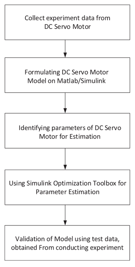
Before starting the estimation process, we need to know system equations that physically represent the DC Servo Motor. The dynamic parameters of the Servo motor can be estimated using the Equations (1) to (4). By taking the Laplace Transform of all the above equations and after simplifying, the following transfer function is obtained:
G(s)=θ(s)/Ea(s)=Kt-1/s[(Ra+sLa)(Jm+Dm)+ Kt2]
G(s)=θ(s)/ Ea(s)=Kt/[(JmLa)s3+RaJm+DmLa)s2+(DmRa+Kt2)s]
After finding Values of K, Tp1, and Tp2, we can find numerical values of servo motor parameters by evaluating Equation (6) and process model transfer function Equation (8).
P(s)=K/s(1+Tp1s)(1+ Tp2s)
P(s)=K/Tp1Tp2s3+(Tp1+ Tp2)s2+s
Evaluating coefficients of (6) and (8), we get
Tp1Tp2=JmLa
RaJm+ DmLa= Tp1+ Tp2
DmRa+Kt2=1
The value of Ra is assumed to find other parameters by solving and putting values in other equations. We get the following values:
Jm=9.027e-3Ω
Kt=4.943e-3 (N.m/A)
Dm=0.518 (N.m/rad/sec)
Ra=1.93Ω
La=2.348e-3H
The estimated values are about 90% closer to the actual measurements.
Parameter estimation using system identification toolbox
We obtain two measured data sets for estimation and validation min and mout are measured input and We obtain two measured data sets for estimation and validation and mout are measured input and output that will be used for estimation and vin and vout are measured input and output that will be used for validation of the model. The next step is to convert input and output data in the MATLAB workspace to the iddata variable. This can be done by using the following command:
data = iddata (output, input, Ts)
where Ts is a sampling time that is 0.005 s.
Comparison of presented techniques
The article presented a comparison of the three popular methods for estimating the parameters of the DC servo motor system. The conventional method using the comparing coefficient method is an easy one but lacks accuracy in terms of achieving experimental results. The second method using the parameter estimation toolbox provided the highest accuracy.
The third method was the system identification technique that provided an accurate response less than the parameter estimation toolbox. The parameter estimation technique is also relatively less complex and requires less computational cost as compared to other techniques found in the literature mentioned earlier.
Parameters vary with time due to the depreciation and aging effect which reduces performance, therefore, to overcome this problem, motor parameters should be updated and different techniques should be used for this purpose. All the previously developed methods are built upon parameter knowledge of the accurate model.
The techniques presented in the literature are much complex and require huge computational costs making these unattractive for common DC servo motor parameter estimation purposes. The contributions of the article are summarized as:
(1) The first-principle model of the DC servo motor is developed and comparing coefficients method has been used to determine the system parameters.
(2) The parameter estimation toolbox has been used to estimate the parameters and validate the response of the system.
(3) A system identification toolbox has been used to estimate parameters.
(4) Comparison of the three methods has been carried out to select the best option for such applications.
Experimental data has been used for the comparison of the estimated response from the techniques. The results show that the parameters obtained from the parameter estimation method give the most accurate simulation results with the least error against the experimental results.

Ea(s)=RaIa(s)+LasIa(s)+ Eb(s)(1)
Tm=KtIa(s)(2)
Tm=(Jms2+Dms)θ(s)(3)
Eb(s)=Kbsθ(s)(4)
Modelling using a parameter estimation technique
In this method, practical measurements from a real DC servo motor are first taken. We then need to identify and specify parameters to estimate, starting with some initial guesses. After feeding this data into the model, parameter values are approximated using a suitable approximation algorithm from the Parameter Estimation Toolbox in Simulink. Five parameters:
Frictional constant Bm, Moment of Inertia Jm, Torque Constant Kt, Inductance La, and Resistance Ra of the servo motor are chosen and are loaded in the Parameter Estimation tool.
Practically, measured data is also loaded for validation of the model. The next step is to plot both measured and simulated data to see how much it matches the current DC Servo Motor's data. If the simulation does not match the measured data, model parameters must be estimated again.
The parameter estimation tool will continue to iterate parameter values until estimation converges or terminates. Plots of measured and simulated data can be overlaid to show how successful is the estimation process.
Modelling using system identification technique
Another technique to estimate parameters for DC Servo Motor is using the System Identification Toolbox if we have measured input and output data. In this study, the estimation validation input, and output data were obtained from MATLAB DC Servo Motor Example. In the following picture shows the Simulink model of the DC Servo motor used for the estimation of motor parameters.
Parameter estimation using comparing coefficient method

Before starting the estimation process, we need to know system equations that physically represent the DC Servo Motor. The dynamic parameters of the Servo motor can be estimated using the Equations (1) to (4). By taking the Laplace Transform of all the above equations and after simplifying, the following transfer function is obtained:
G(s)=θ(s)/Ea(s)=Kt-1/s[(Ra+sLa)(Jm+Dm)+ Kt2]
G(s)=θ(s)/ Ea(s)=Kt/[(JmLa)s3+RaJm+DmLa)s2+(DmRa+Kt2)s]
After finding Values of K, Tp1, and Tp2, we can find numerical values of servo motor parameters by evaluating Equation (6) and process model transfer function Equation (8).
P(s)=K/s(1+Tp1s)(1+ Tp2s)
P(s)=K/Tp1Tp2s3+(Tp1+ Tp2)s2+s
Evaluating coefficients of (6) and (8), we get
Tp1Tp2=JmLa
RaJm+ DmLa= Tp1+ Tp2
DmRa+Kt2=1
The value of Ra is assumed to find other parameters by solving and putting values in other equations. We get the following values:
Jm=9.027e-3Ω
Kt=4.943e-3 (N.m/A)
Dm=0.518 (N.m/rad/sec)
Ra=1.93Ω
La=2.348e-3H
The estimated values are about 90% closer to the actual measurements.
Parameter estimation using system identification toolbox
We obtain two measured data sets for estimation and validation min and mout are measured input and We obtain two measured data sets for estimation and validation and mout are measured input and output that will be used for estimation and vin and vout are measured input and output that will be used for validation of the model. The next step is to convert input and output data in the MATLAB workspace to the iddata variable. This can be done by using the following command:
data = iddata (output, input, Ts)
where Ts is a sampling time that is 0.005 s.
Comparison of presented techniques
The article presented a comparison of the three popular methods for estimating the parameters of the DC servo motor system. The conventional method using the comparing coefficient method is an easy one but lacks accuracy in terms of achieving experimental results. The second method using the parameter estimation toolbox provided the highest accuracy.
The third method was the system identification technique that provided an accurate response less than the parameter estimation toolbox. The parameter estimation technique is also relatively less complex and requires less computational cost as compared to other techniques found in the literature mentioned earlier.
Post a Comment:
You may also like:
Category
Featured Articles
What is a Servo Motor?
 There are some special types of application of electrical motor where rotation of the motor is required for just a certain angle ...
 There are some special types of application of electrical motor where rotation of the motor is required for just a certain angle ...
What are the Basics of Servo Drive?
 Servo motors come in so many types and flavors that it is difficult to define them in a way that is accurate and universally ...
 Servo motors come in so many types and flavors that it is difficult to define them in a way that is accurate and universally ...
Why Use Servo Motor as Test Load?
 Dynamometer is mainly divided into two parts: cabinet and frame, while the frame mainly has the motor under test, torque speed ...
 Dynamometer is mainly divided into two parts: cabinet and frame, while the frame mainly has the motor under test, torque speed ...
What Should Consider Before Using ...
 Servo system is a commonly used control system, widely used in industrial automation. It compares the output signal with the ...
 Servo system is a commonly used control system, widely used in industrial automation. It compares the output signal with the ...
Servo Motor in Food Industry
 In the ever-evolving landscape of the food industry, technological advancements play a pivotal role in enhancing efficiency, ...
 In the ever-evolving landscape of the food industry, technological advancements play a pivotal role in enhancing efficiency, ...