Home » DC Servo Motor » Static and Dynamic Characteristics of DC Servo Motors
Static and Dynamic Characteristics of DC Servo Motors
Static Characteristics of DC Motors
In the general case for all types of DC motor control, the following equations express the steady-state behavior of the motor:
Vt= IaRa + KIfω(1)
Where:
Vt= armature terminal voltage, in volts
I= armature current, in amperes
If= field current, in amperes
R= armature resistance, in ohms
K= a constant
T= torque produced by motor, in newton-meters
ω= speed of armature-shaft rotation, in radians/sec (ω= 2π X rpm/60)
The above general equations may be modified for the following particular types of servo motor control:
(a) Armature control with constant field current
(b) Field control with constant armature current
(c) Field control with constant armature voltage
(d) Series motor control
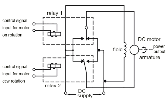
Armature Control with Constant Field Current
Since the field current is constant in this type of servo control, the term KIf, may be combined with a new term K1, and substituted into Eqs. (1) and (2). Then Eq. (2) is substituted into Eq. (1) which is solved for w to obtain
ω= Vt/K1 - TRa/K12
Solving Eq. (1-3) for T
T= K1Vt/Ra - K12ω/Ra(4)
The stall torque TM which occurs at the maximum armature terminal voltage VTm is found from Eq. (4) when T= TM, Vt= VTm, and ω= 0.
TM= K1VTm/Ra(5)
Solving Eq. (1-5) for K1/Ra
K1/Ra= TM/VTm(6)
Substituting Eq. (6) into Eq. (4)
T= TMVT/VTm - TMK1ω/VTm(7)
The no-load speed ωM at the maximum armature terminal voltage VTm is found from Eq. (3) when ω= ωM, VT= VTm, and T= 0.
ωM= VTm/K1(8)
K1/VTm= 1/ωM(9)
Substituting Eq. (1-9) into Eq. (7)
T= TMVT/VTm - TMω/ωM(10)
Dividing Eq. (10) by TM results in
T/TM= VT/VTm - ω/ωM(11)
A plot of T/TM versus ω/ωM characteristics with VT/VTm as a parameter is shown in the following picture. The curves are non-dimensionalized and based on Eq. (11).
The curves can be dimensionalized if the manufacturer's data for a particular motor are known. For example, a DC servo motor has an armature resistance of 5 ohms and a no-load speed of 3000 rpm at a maximum armature terminal voltage of 90 volts.
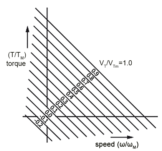
To dimensionalize a plot of T/TM versus ω/ωM characteristics, find the value of no-load speed
ωM in radians/sec and the value of stall torque TM.
From Eq. (1), ω is defined as 2ω X rpm/60. At no-load speed, ω= ωM which is
ωM= 2π X 3000/60
= 314 radians/sec
At the point ω/ωM= 1, the no-load speed ωM is 314 radians/sec. All other points on the ω/ωM axis are dimensioned proportionally.
Substituting 314 for ωM and 90 for VTm in Eq. (9) and solving for K1 gives
K1= VTm/ωM
= 90/314
= 0.286
From Eq. (5), the stall torque is
Tm= K1Vtm/Ra
= 0.286/5 X 90
= 5.15 newton-meters
At the point T/Tm= 1, the stall torque Tm=T=5.15 newton-meters. All other points on the T/Tm axis are dimensioned proportionally. A value of 90 volts is assigned to curve Vt/VTm= 1 (maximum armature voltage), and the other curves are dimensioned proportionally.
In the general case for all types of DC motor control, the following equations express the steady-state behavior of the motor:
Vt= IaRa + KIfω(1)
Where:
Vt= armature terminal voltage, in volts
I= armature current, in amperes
If= field current, in amperes
R= armature resistance, in ohms
K= a constant
T= torque produced by motor, in newton-meters
ω= speed of armature-shaft rotation, in radians/sec (ω= 2π X rpm/60)
The above general equations may be modified for the following particular types of servo motor control:
(a) Armature control with constant field current
(b) Field control with constant armature current
(c) Field control with constant armature voltage
(d) Series motor control

Armature Control with Constant Field Current
Since the field current is constant in this type of servo control, the term KIf, may be combined with a new term K1, and substituted into Eqs. (1) and (2). Then Eq. (2) is substituted into Eq. (1) which is solved for w to obtain
ω= Vt/K1 - TRa/K12
Solving Eq. (1-3) for T
T= K1Vt/Ra - K12ω/Ra(4)
The stall torque TM which occurs at the maximum armature terminal voltage VTm is found from Eq. (4) when T= TM, Vt= VTm, and ω= 0.
TM= K1VTm/Ra(5)
Solving Eq. (1-5) for K1/Ra
K1/Ra= TM/VTm(6)
Substituting Eq. (6) into Eq. (4)
T= TMVT/VTm - TMK1ω/VTm(7)
The no-load speed ωM at the maximum armature terminal voltage VTm is found from Eq. (3) when ω= ωM, VT= VTm, and T= 0.
ωM= VTm/K1(8)
K1/VTm= 1/ωM(9)
Substituting Eq. (1-9) into Eq. (7)
T= TMVT/VTm - TMω/ωM(10)
Dividing Eq. (10) by TM results in
T/TM= VT/VTm - ω/ωM(11)
A plot of T/TM versus ω/ωM characteristics with VT/VTm as a parameter is shown in the following picture. The curves are non-dimensionalized and based on Eq. (11).
The curves can be dimensionalized if the manufacturer's data for a particular motor are known. For example, a DC servo motor has an armature resistance of 5 ohms and a no-load speed of 3000 rpm at a maximum armature terminal voltage of 90 volts.

To dimensionalize a plot of T/TM versus ω/ωM characteristics, find the value of no-load speed
ωM in radians/sec and the value of stall torque TM.
From Eq. (1), ω is defined as 2ω X rpm/60. At no-load speed, ω= ωM which is
ωM= 2π X 3000/60
= 314 radians/sec
At the point ω/ωM= 1, the no-load speed ωM is 314 radians/sec. All other points on the ω/ωM axis are dimensioned proportionally.
Substituting 314 for ωM and 90 for VTm in Eq. (9) and solving for K1 gives
K1= VTm/ωM
= 90/314
= 0.286
From Eq. (5), the stall torque is
Tm= K1Vtm/Ra
= 0.286/5 X 90
= 5.15 newton-meters
At the point T/Tm= 1, the stall torque Tm=T=5.15 newton-meters. All other points on the T/Tm axis are dimensioned proportionally. A value of 90 volts is assigned to curve Vt/VTm= 1 (maximum armature voltage), and the other curves are dimensioned proportionally.
Post a Comment:
You may also like:
Category
Featured Articles
What is a Servo Motor?
 There are some special types of application of electrical motor where rotation of the motor is required for just a certain angle ...
 There are some special types of application of electrical motor where rotation of the motor is required for just a certain angle ...
What are the Basics of Servo Drive?
 Servo motors come in so many types and flavors that it is difficult to define them in a way that is accurate and universally ...
 Servo motors come in so many types and flavors that it is difficult to define them in a way that is accurate and universally ...
Why Use Servo Motor as Test Load?
 Dynamometer is mainly divided into two parts: cabinet and frame, while the frame mainly has the motor under test, torque speed ...
 Dynamometer is mainly divided into two parts: cabinet and frame, while the frame mainly has the motor under test, torque speed ...
What Should Consider Before Using ...
 Servo system is a commonly used control system, widely used in industrial automation. It compares the output signal with the ...
 Servo system is a commonly used control system, widely used in industrial automation. It compares the output signal with the ...
Servo Motor in Food Industry
 In the ever-evolving landscape of the food industry, technological advancements play a pivotal role in enhancing efficiency, ...
 In the ever-evolving landscape of the food industry, technological advancements play a pivotal role in enhancing efficiency, ...